

Untuk mengkonfigurasi H3C S3100-52P saya menggunakan terminal VT220 melalui console port. Ada 2 jenis prompt, yaitu user view dan system view. Untuk bisa melakukan konfigurasi, harus melalui system view.
<h3c>system-view
System View: return to User View with Ctrl+Z.
[H3C]
Untuk membuat Port-Based VLAN pada port 5 s/d 8, perintah barisnya (CLI) adalah sbb :
[H3C]vlan 101
[H3C-vlan101]port Ethernet 1/0/5
[H3C-vlan101]port Ethernet 1/0/6
[H3C-vlan101]port Ethernet 1/0/7
[H3C-vlan101]port Ethernet 1/0/8
[H3C-vlan101]quit
[H3C]save
The configuration will be written to the device.
Are you sure?[Y/N]y
Please input the file name(*.cfg)(To leave the existing filename
unchanged press the enter key):
Now saving current configuration to the device.
Saving configuration. Please wait...
....
Unit1 save configuration flash:/config.cfg successfully
Perintah baris di atas menyebabkan port 5 s/d port 8 menjadi anggota VLAN 101. Jangan lupa untuk menjalankan perintah baris save, agar konfigurasi yang telah dibuat bisa tersimpan ke dalam flash.
Untuk melihat hasil konfigurasi, bisa dilakukan dari User View
<H3C>display vlan all
Pada layar terminal akan terlihat VLAN dan anggotanya. Anggota suatu VLAN dapat dilihat pada Untagged Ports.
Hapus Port VLAN
Misal ingin menghapus port 8 dari VLAN 101, maka langkahnya adalah sbb :
[H3C]vlan 101
[H3C-vlan101]undo port Ethernet 1/0/8
[H3C-vlan101]quit
[H3C]save
Pengujian Port-Based VLAN
Untuk menguji Port-Based VLAN, saya menggunakan 2 komputer yang diberi alamat IP yang se-subnet, yaitu 192.168.130.10/24 dan 192.168.130.11/24. PC1 dikoneksi ke port 1 dan PC2 dikoneksi ke port 2. Pengujian dilakukan dengan perintah baris PING.
Hasil :
- Ping port 1 ke port 3 : OK
- Ping port 1 ke port 5 : FAIL
- Ping port 5 ke port 7 : OK
- Ping port 5 ke port 9 : FAIL
Manual
Sayangnya, througput switch H3C S3100-52P masih 10/100 Mbps, belum sepenuhnya 1000 Mbps. Tidak seperti switch AT-GS950/48.
IP Addressing Configuration
Misal, ingin memberi alamat IP untuk interface 1 dengan alamat 192.168.131.2.
<H3C>system-view
[H3C]interface Vlan-interface 1
[H3C-Vlan-interface1]ip address 192.168.131.2 255.255.255.0
Setelah selesai menjalankan perintah di atas, jangan lupa test dengan PING.
Establishing an HTTP Connection
1) Assign an IP address to VLAN-interface 1 of the switch (VLAN 1 is the default VLAN of the switch). See section 3.5.1 "Telnetting to a Switch from a Terminal" for related information.
2) Configure the user name and the password on the switch for the Web network management user to log in.
Create a Web user account, setting both the user name and the password to “admin” and the user level to 3.
<H3C> system-view
[H3C] local-user admin
[H3C-luser-admin] service-type telnet level 3
[Sysname-luser-admin] password simple admin
3) Establish an HTTP connection between your PC and the switch, as shown in Figure 5-1.
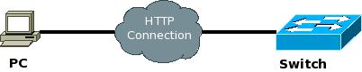
Figure 5-1 Establish an HTTP connection between your PC and the switch
4) Log into the switch through IE. Launch IE on the Web-based network management terminal (your PC) and enter the IP address of the management VLAN interface of the switch in the address bar. (Make sure the route between the Web-based network management terminal and the switch is available.)
5) When the login authentication interface (as shown in Figure 5-2) appears, enter the user name and the password configured in step 2 and click

No comments:
Post a Comment